The MainBoard
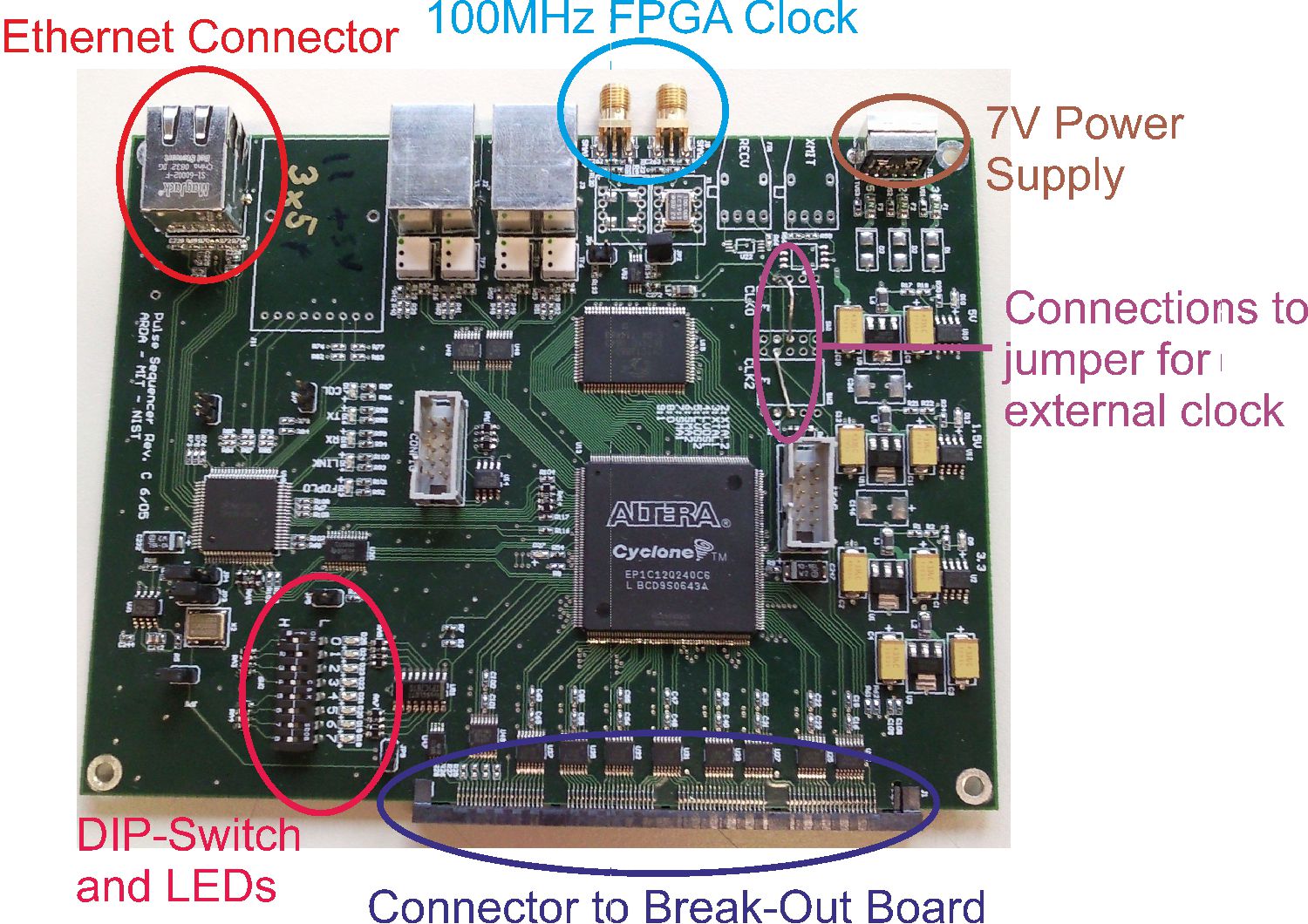
100MHz FPGA Clock
Our experimental setups require the FPGA to operate at 100MHz. And the ethernet connection operates at 100MHz, too. There is a 100MHz quartz on the PCB. In standard configuration, one clock is set to external and one to the quartz on the PCB. Hence, one needs to solder the connections, so that they are both running at the external 100MHz clock because the external clock is most likely much more accurate.
In the picture of the main board, one can see the “Connections to jumper for external clock”. This is the way, it must look like. If one has to solder something there, use the wires that are already on the PCB. If the wires are to short, do not use a flexible wire (=litz wire)!!! Use, for example, a the connection wire of a resistor instead!
7V Power Supply
This PCB has a 5V voltage regulator on it. Hence, the input voltage has to be at least 5.8V. It’s recommended to use 7V as input voltage. The current consumption of the main board can be estimated with about 1A.
Pin 1 of the DIP Switch is the reset. So, in order to invoke a reset, just move the Switch 1 to one other side and then back. When the main board is powered up, or reseted, the LEDs next to the DIP Switch will start to blink for some time. If they don’t blink but the 3 power LEDs are on, there will be something wrong with the clock.
Ethernet Connector
This system is programed through an ethernet connection with a computer. Unfortunately, the ethernet client is programmed very poorly. Hence, one has to take some things into account, when setting up the connection.
The pin 8 of the DIP Switch determines whether the ethernet client is running in DHCP mode or not. IT MUST ALWAYS RUN IN DHCP MODE! Hence, pin 8 must set to off, as shown in the picture. All pulse boxes, or main boards of the pulse boxes, have the same MAC address (= physical network address in a subnet). This address must be unique in a subnet. So, if one has more than one pulse box connected to one router, one has to change the MAC address to become unique. The pins 2-7 of the DIP switch determine the last 6 bits of the MAC address. In order to work, set all pulse box MAC addresses to unique values. If pins 2-7 are all low, the MAC address of the pulse box is 00:01:ca:22:22:20. Accordingly, if pin 2 is high and the rest low, the MAC address is 00:01:ca:22:22:21, and so on. Since the ethernet client works with DHCP, one has to assign the pulse box a certain IP address in the DHCP server. (The DHCP is usually some part of the router). The IP address must be in the 192.168.0.x subnet and the last number has to be 220 or greater!!! If it is not, it won’t work! Since the IP address of the pulse should not change (for convenient operation), log on to your router and assign the MAC address of the router, e.g. 192.168.0.220. (To get the MAC address of the pulse box: If one is logged in at the router, one can see all devices connected to the router. One of them should be the pulse box -> MAC address of the pulse box, or main board of the pulse box.)
Connector to the Break-Out Board
On the main board itself, there are no connectors for our experimental setup. These are all on the break-out board. On the main board, there is just one connector to the break-out board through which all control signals have to go.
Troubleshooting
A first test can be performed by observing the LEDs near the DIP switches after switching on the Box. They should change from one to the next rapidly. If the LEDs take about one second or longer to switch, the clock of the FPGA is not applied.
The configuration of the ehternet can be tested by starting the server of the sequencer2 software. If no ``pulse transfer protocol error` is displayed, the ethernet configuration works.
The main sources of errors are:
- The clock is not connected
- The FPGA core clock and the ethernet clock are not the same
- The firmware is not programmed
Reprogramming the firmware
The firmware for the can be found at
http://pulse-sequencer.sourceforge.net/firmware/sequencer_top-v0_29.pof