The BreakoutBoard
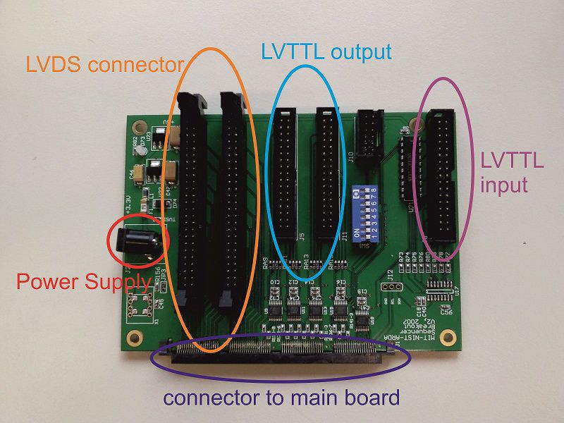
The breakout board provides the connectors for the various Bus systems. The LVTTL inouts and outputs are connected to the digital input and output cards, whioch provide a galvanic isolation. The LVDS bus is connected to the DDS devices that provide an analog RF output.
The connectors
The power conenctor needs to be soldered the connector to the PCB. The problem with this connector is that it is very space-consuming in the pulse box. Since along this side of the main and break-out board, there are no other connectors. One other idea would be to solder the connection wires directly to the PCB. The voltage of this PCB is the same as for the main board. That means 7VDC!
The connection to the mainboard is performed by a SAMTEC connector The company that built the 30 break-out boards was not capable of soldering this connector, too. Hence, one has to solder it oneself. Since there are 128 connections to solder, it’s kind of a pain. One easier way of doing it is to use solder paste and a heat gun, available at the Kasper-Hauser room or at the IQOQI with Gerhard Hendl. It’s very likely that not all connections at soldered perfectly, therefore one needs to check the connections and resolder. On how to check the connections for the individual connectors, please refer to the corresponding section.
Troublehooting
The main reasons for failures on the breakout board are:
- The connector to the mainboard is not soldered correctly A LVDS to
- A LVDS-TTL converter is not soldered correctly
- A LVDS-TTL converter is broken
If the breakout board is working correctly and the LEDs of the output ports do not work when testnig the TTL output channels, the error is located in the digital output board.
LVTTL Input Connectors
A basic test on the 8 trigger inputs is performed by checking the 16 corresponding connections at the main board connector with a continuity tester. One can, of course, repeat the same trick with the voltmeter again but this time in the other direction.
Testing the LVTTL Output Connectors
All pins on the left side (closer to the LVDS connectors) are GND. And the 16 data pins are on the right side starting at the bottom (closer
to the main board connector). One can connect these pins with a test
device, such as the PCBs for the TTL-output signal or a logic analyzer. At this point, Python and the Sequencer are probably already installed and configured. Open a shell, change to the directory of the sequencer and start Python from there. Then type:
from tests.test_hardware import *
and to test if the connection to the pulse box works, type:
ht = HardwareTests()
In order to set all TTL output pin to high, type:
ht.test_ttl_set()
or:
ht.test_ttl_set(65535)
To set them all to low, type:
ht.test_ttl_set(0)
With the test device, one should now be able to see if all connections correctly transport LOWs and HIGHs. Since it can be hard to find the right connections from a specific pin number to the pin on the main board connector, there is also the possibility to check the voltages at the resistors next to the main board connector with a voltmeter. After checking some connections, one will easily be able to determine between good and bad connections. (But don’t forget this PCB has a top and a bottom side.)